빠른 답변: An 800V EV contactor must be selected for the battery’s maximum charged voltage and transients, not the nominal architecture label. It must also satisfy insulation coordination, DC make and break duty, bidirectional current, thermal rise, precharge, short-circuit coordination, coil-driver behavior, feedback diagnostics, environmental stress, and the vehicle’s required switching life.
이 엔지니어링 가이드에서는 배터리 팩, BMS, 테스트, 소싱, 서비스 팀을 위한 검토 가능한 순서로 이 주제를 구성합니다. 모든 등급 및 안전 결정은 최종 애플리케이션과 현재 제조사의 문서와 연계하여 이루어지며, 실제 제품군을 참고 자료로 사용합니다.
결정도표
| 운영 상태 | 예상되는 증거 | 엔지니어링 중심 |
|---|---|---|
| Maximum working voltage | Highest charged pack plus defined operating tolerance | Use model-specific DC ratings and system transients |
| Insulation | Clearance, creepage, dielectric and pollution environment | Coordinate pack, enclosure, altitude and service access |
| Current duty | Traction, regeneration, charging and fault opening | Separate continuous, peak, make and break conditions |
| 보호 | Fuse, pyrofuse, precharge and discharge coordination | Prove fault energy and safe isolation sequence |
제품 참조 및 적용 범위
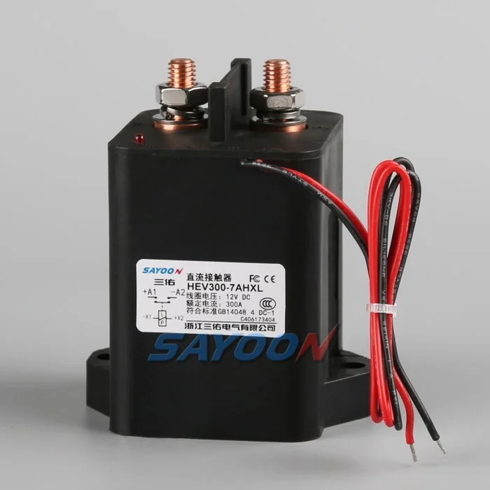
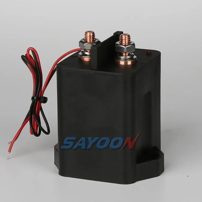
그 HEV300 high-voltage sealed DC contactor 여기서 보여지는 것은 실제 Sayoon 제품의 참조입니다. 검토해 보세요. 고전압 DC 접촉기 범위 접경하는 전류 등급에 적용됩니다. 해당 이미지는 해당 차량에 대한 승인을 의미하지 않습니다. 최종 부품 번호, 코일 옵션, 도면, 전기적 성능, 절연성, 환경 적합성, 수명 및 보호 기능의 조합을 함께 검토해야 합니다.
800V is an architecture class, not one fixed voltage
An “800V” vehicle does not operate at exactly 800 V in every state. The pack voltage changes with cell chemistry, series count, state of charge, temperature, and load. Charging and regeneration can place the pack near its maximum charged voltage, while switching transients can briefly add stress. Specify the minimum, nominal, maximum continuous, and defined transient voltages.
Select the contactor using the manufacturer’s approved DC voltage conditions and insulation data. Do not approve a device merely because its name includes 800 V or because an AC insulation number looks high.
Insulation coordination and altitude
Higher voltage increases the importance of creepage, clearance, dielectric withstand, pollution degree, material group, sealing, and the distance to grounded metal. Altitude reduces air density and can require larger clearances or derating. The completed battery junction box—not the contactor alone—must maintain the required insulation under condensation, contamination, vibration, and service conditions.
Review terminal spacing, busbar geometry, mounting hardware, sensors, connector pins, and enclosure ribs. Use the standards and vehicle requirements adopted by the project; do not copy a spacing number without matching the environment and overvoltage category.
DC interruption at higher voltage
A DC arc does not naturally cross zero. At higher voltage, the contactor’s arc-control system, contact gap, opening speed, magnetic field, gas sealing, and current direction become critical. Continuous current and breaking current are different ratings. Confirm make and break performance at the maximum voltage, actual load inductance, and the required polarity or bidirectional condition.
Normal control should reduce inverter or charger current before opening when safe. Emergency opening, crash isolation, and fault interruption require separately qualified duties and protection coordination.
Thermal current and power relationships
For the same power, higher voltage can reduce current, but that does not automatically make the contactor cooler. Fast charging, launch, regeneration, enclosure temperature, terminal resistance, and busbar design still determine heating. Contact loss is approximately I²R, and joint resistance outside the contactor can become equally important.
Use measured current profiles and thermal boundary conditions. Verify temperature rise at the terminals and body with the production busbar, torque, conductor size, airflow, and neighboring fuse or pyrofuse.
Precharge and discharge
The inverter DC link must be charged through a controlled path before the main contactor closes. At 800V-class levels, the stored energy and make-current consequence are substantial. Size the resistor and precharge contactor for maximum voltage difference, capacitance, pulse energy, repeat duty, and temperature. Close the main contactor only after measured voltages meet the approved ratio and timing window.
After opening, verify that the discharge circuit reduces the load-side bus to the vehicle-defined safe threshold. A timer without voltage confirmation cannot prove the bus is safe.
Bidirectional current and charging compatibility
Traction current flows from the battery to the inverter, while regeneration and DC charging send current toward the battery. Confirm that the main contactor carries and switches the required directions. Some 800V vehicles also interact with lower-voltage chargers through a booster or reconfiguration strategy, which can create additional contactor states and switching sequences.
Map each configuration and prevent two contactors from creating an unintended parallel or series path. Add feedback and bus-voltage plausibility checks for every state.
Short-circuit and crash coordination
Define the prospective pack fault current, battery impedance, cable and busbar inductance, fuse or pyrofuse clearing behavior, and the contactor’s required withstand or interruption duty. The contactor is not a substitute for a fuse, and a fuse does not provide repeatable functional switching. The safety concept should state which device acts first and what energy remains downstream.
After a crash event, inhibit reclose, verify isolation and discharge, and require inspection of the contactor, terminals, busbars, fuse, precharge branch, and trigger circuits before service release.
Coil drive, feedback and EMC
The low-voltage coil driver must provide reliable pull-in during supply sag and controlled release during faults. Suppression changes opening time and driver stress. Capture coil current, command, auxiliary feedback, pack voltage, and load-side voltage on one time base. Use independent voltage evidence to detect welded or stuck-open main contacts.
At 800V-class switching levels, layout, shielding, grounding, and measurement isolation affect EMC and diagnostic accuracy. Validate the production harness and controller, not only a short bench setup.
RFQ and qualification checklist
Provide minimum, nominal, maximum and transient pack voltage; continuous and peak currents; current direction; make and break waveforms; DC-link capacitance; precharge and discharge requirements; short-circuit source; protection clearing time; insulation environment; altitude; temperature; vibration; sealing; coil voltage; driver and suppression; auxiliary logic; life; mounting; busbars; and required approvals.
The HEV300 shown here is a product reference. Confirm the exact voltage, current, insulation, coil, and endurance data for the final model and production installation.
수용 기록
완전 부품 번호, 도면 개정 버전, 코일 옵션, 단자 기능, 전압 범위, 전류 파형, 전환 상태, 사전 충전 및 방전 세부 정보, 드라이버 및 억제 기능, 보조 로직, HVIL 상태, 보호 기능, 주변 온도 및 인클로저 온도, 장착 방향, 도체 및 버스바 세부 정보, 계측 장치 위치, 교정 상태, 소프트웨어 버전, 통과/실패 제한값을 포함하는 한 개의 제어된 레코드를 생성합니다. 카탈로그 값과 측정값 간의 차이를 구분하고, 일반적인 값을 삽입하기보다는 누락된 증거를 공개 조치로 표시합니다.
중요한 경계점에서의 테스트: 낮은 및 높은 코일 공급, 찬 및 뜨거운 조건, 가장 긴 승인된 하네스, 반복적인 사이클, 그리고 안전 개념에 명시된 비정상 상태. 한 번의 기준 시간으로 제어 명령, 코일 전압 및 전류, 보조 피드백, 팩 전압, 부하 측 전압, 그리고 결함 경고 신호를 기록합니다. 설명되지 않은 불일치 후 자동 재시도 중지, 저장된 에너지를 분리하고 최초 결함 증거를 보존합니다. 설정 및 단자 배치 사진 촬영, 모든 프로브 지점 식별, 생산 목적의 하네스 및 버스바 기록, 그리고 각 임계값의 안전성을 설명합니다. 열 안정화 후 및 계획된 내구성 블록 후 대표적인 샘플을 반복합니다. 운전사, 시험 날짜, 샘플 식별, 그리고 생산 조립과 동일한 승인된 기준선에 따른 모든 편차를 포함합니다. 이후 성공적인 사이클은 이전 결함이 지워지지 않도록 해야 합니다. 이러한 기록은 교체 샘플, 공급업체 개정, 펌웨어 업데이트, 또는 하네스 변경을 동일한 승인된 기준선과 비교할 수 있도록 합니다.
Also verify labeling, service documentation, isolation points, and change-control approvals before the production design is released to vehicle assembly.
관련 사이운 가이드
사용하세요 직류(DC) 접촉기 선정 가이드, 안전 접촉기 테스트 워크플로, 그리고 오픈 및 폐업 시간 안내 보완적 결정에 대해서. feedback plausibility guide explains command, auxiliary, and bus-voltage correlation.
교육용 비디오
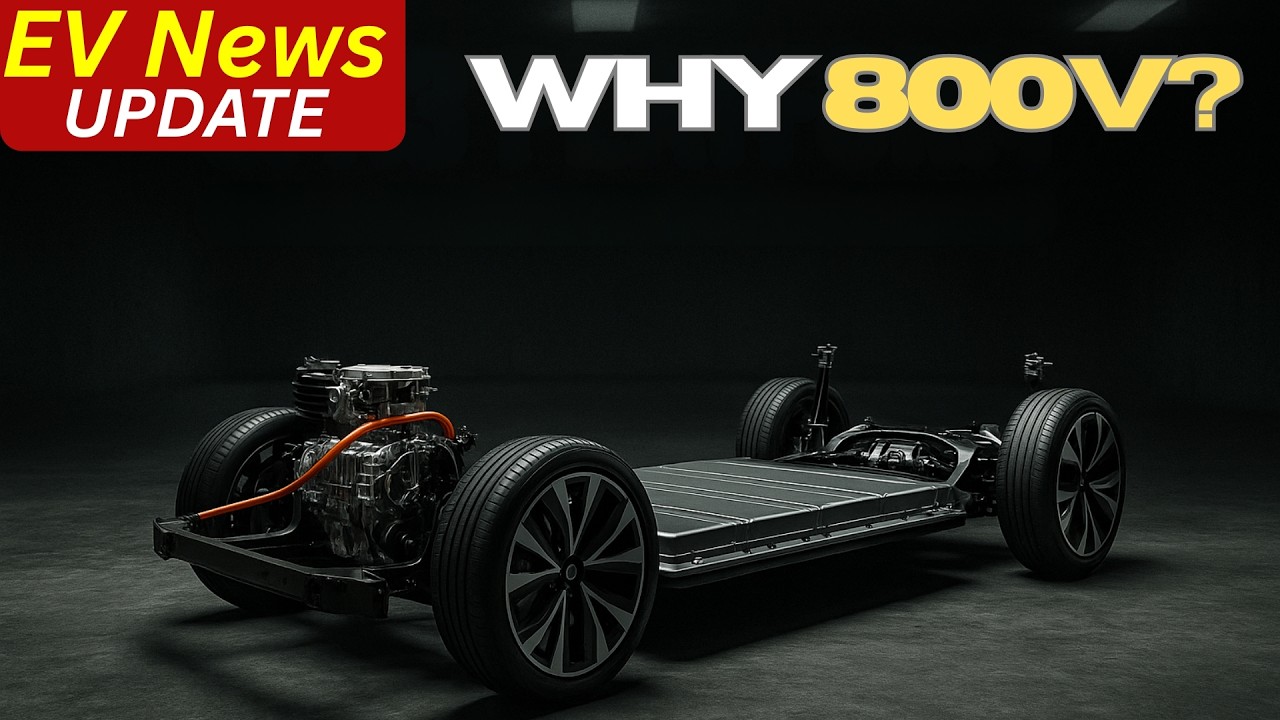
WHAT IS 800-Volt Architecture in EVs? by EV Zone provides visual background related to this engineering review. It does not replace the written requirements, product data, or vehicle safety procedure.
자주 묻는 질문
What is the most important check for 800v ev contactor?
최대 전압과 실제 스위칭 파형을 기준으로 시작하여, 정확한 접점 데이터, 제어 시퀀스, 설치, 그리고 결함 현상을 함께 확인합니다.
보조 연락자가 주요 연락자들의 건강을 입증할 수 있는가?
아니요. 보조 피드백 보고 메커니즘은 한계 내에서 작동합니다. 버스 전압, 타이밍, 코일 전류 및 회로 상태를 독립적인 증거로 사용하십시오.
명목 전류 등급을 완전한 선택 규칙으로 사용할 수 있습니까?
아닙니다. 연속 전류, 전류 흐름, 정지 전류, 전압, 온도, 극성, 수명, 절연성 및 보호 기능의 조화는 별개의 조건입니다.
RFQ와 함께 보내야 하는 정보는 무엇인가요?
전압 및 전류 파형, 스위칭 시퀀스, 환경, 코일 및 드라이버 세부 정보, 피드백 로직, 보호 기능, 장착 방식, 수명 목표 및 필요한 테스트 증거를 보내주십시오.
권위 있는 참고문헌
- SAE J1766 electric and hybrid vehicle safety practice
- 텍사스 인스트루먼트, EV 및 HEV용 고전압 접촉기 개발
- NHTSA electric-vehicle safety information
- Berkeley power electronics technical report
차량 프로그램에서 채택한 에디션과 요구 사항을 사용하십시오. 표준 및 공급업체 데이터는 변경될 수 있으며, 책임 있는 엔지니어링 팀은 최종 설계 검증을 수행해야 합니다.





