Snel antwoord: An 800V EV contactor must be selected for the battery’s maximum charged voltage and transients, not the nominal architecture label. It must also satisfy insulation coordination, DC make and break duty, bidirectional current, thermal rise, precharge, short-circuit coordination, coil-driver behavior, feedback diagnostics, environmental stress, and the vehicle’s required switching life.
Deze technische gids zet het onderwerp om in een herhaalbare volgorde voor batterijpacks, BMS'en, tests, sourcing en serviceafdelingen. Het maakt gebruik van de echte productfamilie als referentie, terwijl elke beoordeling en veiligheidsbeslissing is gekoppeld aan de uiteindelijke toepassing en de huidige fabrikadoppervlakken.
Besluitkaart
| Werkende toestand | Onderzochte gegevens | Engineeringfocus |
|---|---|---|
| Maximum working voltage | Highest charged pack plus defined operating tolerance | Use model-specific DC ratings and system transients |
| Insulation | Clearance, creepage, dielectric and pollution environment | Coordinate pack, enclosure, altitude and service access |
| Current duty | Traction, regeneration, charging and fault opening | Separate continuous, peak, make and break conditions |
| Bescherming | Fuse, pyrofuse, precharge and discharge coordination | Prove fault energy and safe isolation sequence |
Productreferentie en toepassingsgrenzen
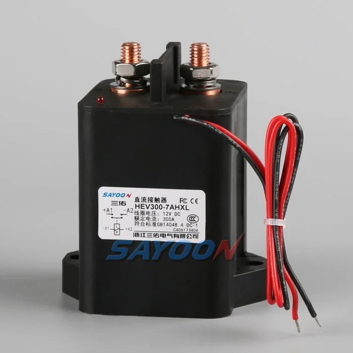
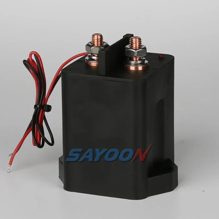
De HEV300 high-voltage sealed DC contactor Het hier getoonde is een echt referentieproduct van Sayoon. Bekijk de Uitgebreid assortiment hoogspannings-DC-contactoren Voor naastgelegen stroomklassen. Het beeld en de familienaam geven geen goedkeuring voor een bepaald voertuig aan. Het definitieve onderdeelnummer, de coiloptie, de tekening, de elektrische belasting, de isolatie, het milieu, de levensduur en de coördinatie van de bescherming moeten samen worden beoordeeld.
800V is an architecture class, not one fixed voltage
An “800V” vehicle does not operate at exactly 800 V in every state. The pack voltage changes with cell chemistry, series count, state of charge, temperature, and load. Charging and regeneration can place the pack near its maximum charged voltage, while switching transients can briefly add stress. Specify the minimum, nominal, maximum continuous, and defined transient voltages.
Select the contactor using the manufacturer’s approved DC voltage conditions and insulation data. Do not approve a device merely because its name includes 800 V or because an AC insulation number looks high.
Insulation coordination and altitude
Higher voltage increases the importance of creepage, clearance, dielectric withstand, pollution degree, material group, sealing, and the distance to grounded metal. Altitude reduces air density and can require larger clearances or derating. The completed battery junction box—not the contactor alone—must maintain the required insulation under condensation, contamination, vibration, and service conditions.
Review terminal spacing, busbar geometry, mounting hardware, sensors, connector pins, and enclosure ribs. Use the standards and vehicle requirements adopted by the project; do not copy a spacing number without matching the environment and overvoltage category.
DC interruption at higher voltage
A DC arc does not naturally cross zero. At higher voltage, the contactor’s arc-control system, contact gap, opening speed, magnetic field, gas sealing, and current direction become critical. Continuous current and breaking current are different ratings. Confirm make and break performance at the maximum voltage, actual load inductance, and the required polarity or bidirectional condition.
Normal control should reduce inverter or charger current before opening when safe. Emergency opening, crash isolation, and fault interruption require separately qualified duties and protection coordination.
Thermal current and power relationships
For the same power, higher voltage can reduce current, but that does not automatically make the contactor cooler. Fast charging, launch, regeneration, enclosure temperature, terminal resistance, and busbar design still determine heating. Contact loss is approximately I²R, and joint resistance outside the contactor can become equally important.
Use measured current profiles and thermal boundary conditions. Verify temperature rise at the terminals and body with the production busbar, torque, conductor size, airflow, and neighboring fuse or pyrofuse.
Precharge and discharge
The inverter DC link must be charged through a controlled path before the main contactor closes. At 800V-class levels, the stored energy and make-current consequence are substantial. Size the resistor and precharge contactor for maximum voltage difference, capacitance, pulse energy, repeat duty, and temperature. Close the main contactor only after measured voltages meet the approved ratio and timing window.
After opening, verify that the discharge circuit reduces the load-side bus to the vehicle-defined safe threshold. A timer without voltage confirmation cannot prove the bus is safe.
Bidirectional current and charging compatibility
Traction current flows from the battery to the inverter, while regeneration and DC charging send current toward the battery. Confirm that the main contactor carries and switches the required directions. Some 800V vehicles also interact with lower-voltage chargers through a booster or reconfiguration strategy, which can create additional contactor states and switching sequences.
Map each configuration and prevent two contactors from creating an unintended parallel or series path. Add feedback and bus-voltage plausibility checks for every state.
Short-circuit and crash coordination
Define the prospective pack fault current, battery impedance, cable and busbar inductance, fuse or pyrofuse clearing behavior, and the contactor’s required withstand or interruption duty. The contactor is not a substitute for a fuse, and a fuse does not provide repeatable functional switching. The safety concept should state which device acts first and what energy remains downstream.
After a crash event, inhibit reclose, verify isolation and discharge, and require inspection of the contactor, terminals, busbars, fuse, precharge branch, and trigger circuits before service release.
Coil drive, feedback and EMC
The low-voltage coil driver must provide reliable pull-in during supply sag and controlled release during faults. Suppression changes opening time and driver stress. Capture coil current, command, auxiliary feedback, pack voltage, and load-side voltage on one time base. Use independent voltage evidence to detect welded or stuck-open main contacts.
At 800V-class switching levels, layout, shielding, grounding, and measurement isolation affect EMC and diagnostic accuracy. Validate the production harness and controller, not only a short bench setup.
RFQ and qualification checklist
Provide minimum, nominal, maximum and transient pack voltage; continuous and peak currents; current direction; make and break waveforms; DC-link capacitance; precharge and discharge requirements; short-circuit source; protection clearing time; insulation environment; altitude; temperature; vibration; sealing; coil voltage; driver and suppression; auxiliary logic; life; mounting; busbars; and required approvals.
The HEV300 shown here is a product reference. Confirm the exact voltage, current, insulation, coil, and endurance data for the final model and production installation.
Accreditatiegegevens
Maak een gecontroleerde record aan met het volledige onderdeelnummer, teken revisie, coil-optie, terminalfuncties, spanningsbereik, stroomgolfvorm, schakelstatus, precharge- en ontlaadgegevens, driver en suppressie, hulplogica, HVIL-status, bescherming, omgevings- en behuizingstemperaturen, montagerichting, details van geleiders en busbars, instrumentlocaties, kalibratiestatus, softwareversie en door- of niet-doorgaande limieten. Verdeel gemeten waarden af van de cataloguswaarden en markeer ontbrekende gegevens als open actie in plaats van een typische waarde toe te voegen.
Test op de belangrijkste parameters: lage en hoge spoelspanning, koude en warme omstandigheden, langste goedgekeurde kabelverbinding, herhaalde cycli en de abnormale toestand zoals omschreven in het veiligheidsconcept. Capture-commando, spoelspanning en -stroom, hulpvolgverwerking, packvoltage, laadzijdevoltage en foutmeldingen op één tijdbasis. Stop automatisch herhalingen na een onverklaarbaar mismatch, isoleer opgeslagen energie en bewaar bewijs van de eerste storing. Fotografeer de installatie en de terminalindeling, identificeer alle sondepunten, registreer de kabelverbinding en busbar volgens de productievoorgestelde configuratie en leg uit waarom elk drempelwaarde veilig is. Herhaal een representatief monster na thermische stabilisatie en na de geplande endurance-blok. Vermeld de operator, testdatum, identiteit van de monsterstalen en alle afwijkingen van de productieconfiguratie. Een later succesvol cyclus mag geen eerder probleem verwijderen. Deze gegevens maken een vervangend monster, revisie van de leverancier, firmware-update of kabelverbindingswijziging mogelijk, die vergeleken kunnen worden met dezelfde goedgekeurde basislijn.
Also verify labeling, service documentation, isolation points, and change-control approvals before the production design is released to vehicle assembly.
Gerelateerde Sayoon-gidsen
Gebruik de Selectiehandleiding voor DC-relais, veilig contactor testworkflow, en Gids voor openingstijden en sluitingstijden voor aanvullende beslissingen. feedback plausibility guide explains command, auxiliary, and bus-voltage correlation.
Educatieve video
WHAT IS 800-Volt Architecture in EVs? by EV Zone provides visual background related to this engineering review. It does not replace the written requirements, product data, or vehicle safety procedure.
Bekijk de educatieve video op YouTube.
Veelgestelde vragen
What is the most important check for 800v ev contactor?
Start met de maximale spanning en de werkelijke schakelgolf, controleer vervolgens samen de precieze contactorgegevens, de besturingsesequentie, de installatie en het gedrag bij storingen.
Kan een hulpcontact een bewijs leveren dat de hoofdcontacten gezond zijn?
Nee. Het mechanisme voor hulpvol feedbackrapportage blijft binnen zijn grenzen. Gebruik busspanning, timing, spoelstroom en de status van het circuit als onafhankelijke bewijzen.
Kan een nominale stroomsterkte worden gebruikt als de volledige selectieregel?
Nee. Continu stroom, stroomstoring, spanningsstoring, temperatuur, polariteit, levensduur, isolatie en beschermingscoördinatie zijn afzonderlijke vereisten.
Welke informatie moet bij een RFQ worden verstrekt?
Stuur voltage- en stroomgolven, schakelverloop, omgeving, details over spoel en driver, feedbacklogica, bescherming, montage, levensduurdoelstelling en vereiste testgegevens mee.
Betrouwbare referenties
- SAE J1766 electric and hybrid vehicle safety practice
- Texas Instruments, hoogspanningscontactoren voor elektrische voertuigen en hybride voertuigen
- NHTSA electric-vehicle safety information
- Berkeley power electronics technical report
Gebruik de uitvoering en vereisten die zijn vastgesteld door het voertuigprogramma. Normen en gegevens van leveranciers kunnen veranderen, en het verantwoordelijke technische team moet het definitieve ontwerp bevestigen.





